Introduction
You can run a Field Effect virtual sensor as a virtual machine (VM) on Proxmox VE. This article explains how to size and create the network sensor VM and describes the supported ways to send network traffic to it.
Before you begin
Make sure you have:
- Proxmox VE host with enough resources for the network sensor.
- Access to the Field Effect MDR Portal.
- Outbound interner access for the sensor's management interface. See Virtual Sensors: Overview to learn more.
- Working knowledge of Proxmox and Linux networking. The network traffic options in this article depend on your environment and may need to be adapted.
NOTE: Let Field Effect Support know which network traffic option you plan to use. We configure traffic capture on the sensor to match.
Step 1: Choose how network traffic will reach the sensor
Review the Network Traffic Options below and pick the option that best suits your environment. The option you choose determines which network interfaces the sensor VM needs.
Step 2: Create the Sensor VM
- Download the installer ISO. See the following articles for more:
- Upload the ISO to Proxmox.
- Create a VM from the ISO using the Recommended VM Sizing and Proxmox VM Settings (outlined below)
- Attach the first network interface to a bridge with outbound internet access. This is the sensor's management interface required for every setup.
- Add any additional interfaces as per your chosen network traffic option (outlined below).
- Start the VM. The installer runs automatically and needs no input.
Once the sensor is online, contact Field Effect Support to confirm that it is connected and receiving traffic.
Recommended VM sizing
If you need to capture more than 1 Gbps, contact Field Effect Support before deploying.
Size the sensor according to the maximum amount of network traffic it will capture.
| Max captured bandwidth | vCPU | RAM | Disk | Disk IOPS (sustained) | Disk throughput (sustained) |
|---|---|---|---|---|---|
| 100 Mbps | 2 | 8 GB | 512 GB SSD | 500 | 100 MB/s |
| 500 Mbps | 4 | 16 GB | 1024 GB SSD | 500 | 100 MB/s |
| 1 Gbps | 8 | 32 GB | 1024 GB SSD | 5,000 | 200 MB/s |
The disk must be SSD-backed. If you use shared or network storage (such as Ceph, NFS or iSCSI), it must sustain the IOPS and throughput above with latency comparable to local SSD.
Proxmox VM settings
| Setting | Value |
|---|---|
| BIOS | OVMF (UEFI), machine type q35 |
| EFI disk | Added, with Pre-Enroll keys cleared (Secure Boot off) |
| CPU | Type host, 1 socket, cores from the sizing table |
| Memory | From the sizing table, with Ballooning Device cleared |
| Disk | Bus SCSI, controller VirtIO SCSI single, IO thread on, cache Write back, Discard on, SSD emulation on |
| Network devices | Model VirtIO (paravirtualized) for every interface |
| QEMU Guest Agent | On (Options > QEMU Guest Agent). The sensor installs qemu-guest-agent automatically. |
| Start at boot | On |
Network traffic options
Field Effect supports the three options below. Each one takes traffic from a physical switch or router and sends it to the sensor.
Important: For any option that uses a VM network device, clear Firewall on the sensor's capture or ERSPAN interface (VM > Hardware > Network Device). When the firewall is on, Proxmox can place a firewall bridge between the host bridge and the VM, which may drop mirrored or GRE traffic.
These examples are for reference. Your switch, host hardware and network layout may require a different configuration.
Option 1: Switch port mirror with PCI passthrough
Your switch mirrors traffic to a dedicated physical NIC on the Proxmox host. That NIC is passed through to the sensor VM using PCI passthrough, so the sensor receives the mirrored traffic directly.
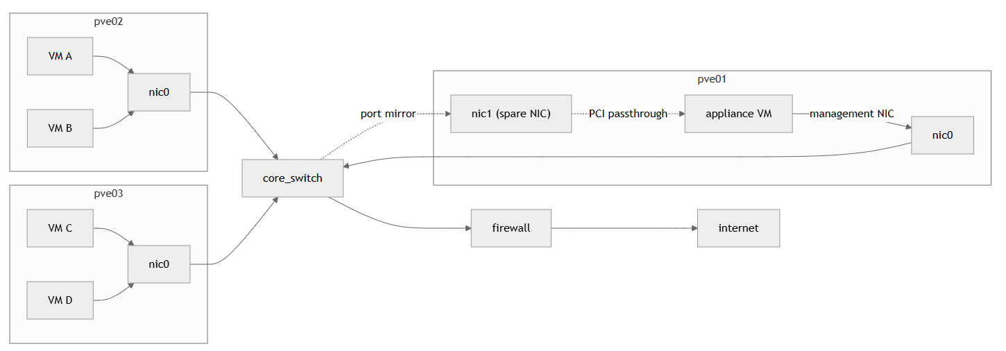
Requirements:
- A NIC on the Proxmox host that is used for nothing else.
- A switch that can mirror (SPAN) the traffic you want monitored to the port connected to that NIC.
- IOMMU and PCI passthrough enabled on the host. See the Proxmox PCI Passthrough guide.
- Ideally, the NIC is in its own IOMMU group. If ports on the card share a group, all devices in that group are passed to the VM together, which can remove other ports from the host. This depends on your hardware.
Steps
- Configure the switch to mirror the desired traffic to the port connected to the spare NIC, with VLAN tags preserved.
- Add the NIC to the sensor VM as a PCI device (VM > Hardware > Add > PCI Device).
- The sensor receives the mirrored traffic on that interface, with VLAN tags as sent by the switch.
Things to know
- When the VM stops, the NIC stays bound to
vfio-pci. It returns to the host only when it is rebound to its own driver or the host restarts. - A VM with a passed-through device is tied to its host. In a cluster, the sensor must run on the host with the mirror NIC, and HA migration is disabled for it.
Option 2: Switch port mirror with a Linux bridge
The network setup is the same as Option 1, but instead of passing the NIC through, a Linux bridge on the spare NIC delivers the mirrored traffic to the sensor VM.
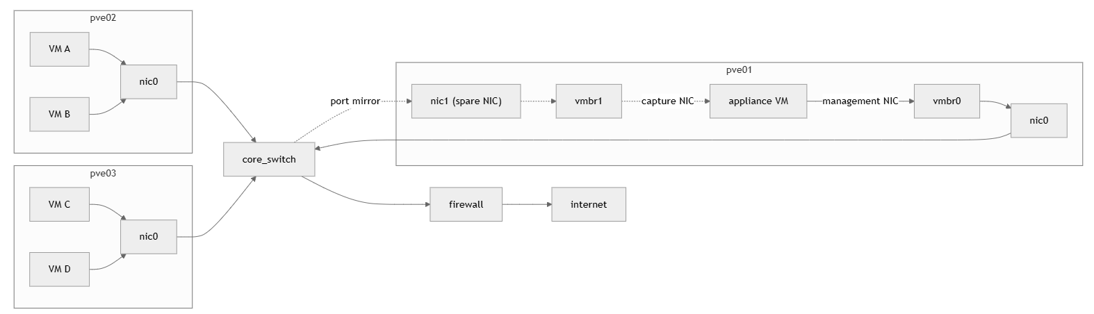
Requirements
- A NIC on the Proxmox host that is used for nothing else.
- A switch that can mirror (SPAN) the traffic you want monitored to the port connected to that NIC.
Steps
- Configure the switch to mirror the desired traffic to the port connected to the spare NIC, with VLAN tags preserved.
- On the Proxmox host, create a Linux bridge with the spare NIC as its only port and no IP address (node > System > Network > Create > Linux Bridge).
- Example: `/etc/network/interfaces` entry (replace `nic1` with your spare NIC's name, and `vmbr1` with the next free bridge name on the host):
auto nic1
   iface nic1 inet manual

   auto vmbr1
   iface vmbr1 inet manual
       bridge-ports nic1
       bridge-stp off
       bridge-fd 0
       bridge-ageing 0
- Example: `/etc/network/interfaces` entry (replace `nic1` with your spare NIC's name, and `vmbr1` with the next free bridge name on the host):
- Add a second network interface to the sensor VM and attach it to
vmbr1. - The sensor receives the mirrored traffic on that interface.
Things to know
- Leave VLAN aware off on
vmbr1, and don't set a VLAN tag on the sensor's capture interface. This lets tagged frames pass through the bridge unchanged. bridge-ageing 0is required. It makes the bridge forward every frame to the sensor. Without it, the bridge learns MAC addresses from the mirrored traffic and drops most unicast frames, so the sensor sees very little traffic. Because the sensor is the only other port on this bridge, this setting doesn't affect other VMs.- In a cluster, the sensor must run on the host with the mirror NIC, and HA migration is disabled for it.
Option 3: ERSPAN from a switch
If your switches or routers support ERSPAN, they can send mirrored traffic over the network to an interface on the sensor. No dedicated NIC is needed. For requirements and limitations, see ERSPAN Support.
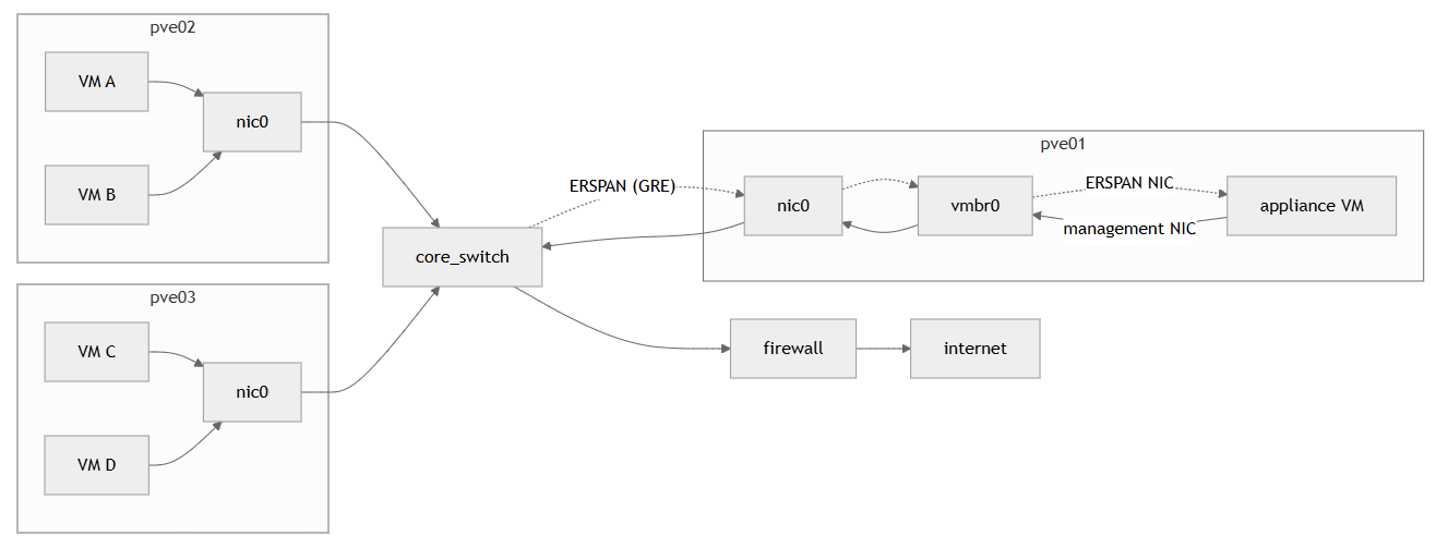
Things to know
- If
vmbr0is VLAN aware, assign the sensor's ERSPAN interface the VLAN tag that can reach the switch's ERSPAN destination address. - ERSPAN Type II adds 36 bytes to each mirrored frame, so a full-size VLAN-tagged frame arrives as a 1554-byte packet. Every hop from the switch to the senssor, including the host NIC and
vmbr0, needs an MTU of at least 1554. Otherwise, full-size frames are dropped or truncated. A VM network device with no MTU set uses the bridge's MTU.
Was this article helpful?
That’s Great!
Thank you for your feedback
Sorry! We couldn't be helpful
Thank you for your feedback
Feedback sent
We appreciate your effort and will try to fix the article